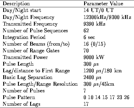
Table 3.2: SuperDARN operating parameters during standard scanning mode (this is an example from Saskatoon on 8 March 1995, 0 UT)
The SuperDARN radar consists of three main components: the HF hardware with transmitter and receiver, a control computer that is responsible for exact timing and sequencing of the HF system, and a second computer responsible for online processing of the data. Table 3.2 lists typical operating parameters for the SuperDARN radars.

Table 3.2: SuperDARN operating parameters during standard scanning mode
(this is an example from Saskatoon on 8 March 1995, 0 UT)
The operating frequency has to be different for day and night times, since the electron density changes considerably due to photo-ionization of the atmosphere by sunlight during the day. The actual frequency at which the radar operates is usually different from the normal values listed in Table 3.2. Before starting a new beam scan, a clear frequency search routine is used to choose a frequency for which the receiver indicates the lowest noise level. A number of pulse sequences are transmitted during the integration period, so that signal averaging can be used. This is required for the determination of the ACFs, as will be evident later from the analysis presented. The normal operating mode scans over 16 beam directions and distinguishes 70 ranges (or range gates) yielding complex ACFs for 1120 locations every 2 minutes. This two minute boundary is chosen for the beginning of a new scan. All radars are synchronized by means of GPS clocks. A large amount of HF power is transmitted in several short pulses during a sequence, followed shortly after the first pulse has been sent out by a period of reception and sampling of the backscattered signal strength.
The pulse pattern is well chosen to yield an optimal basis for determining the reflected power level and the data points of the ACF, as will be described later. The radar control software generates the ACFs through integration over several pulse sequences (normally around 60 sequences during the roughly 7 s dwell time for a given beam position) and store them. The assumption is that the scatterers in the F-region can be considered stationary for this 7 s period. Additionally, an ACF fitting procedure further qualifies the data in a second, real-time processing step by calculating Doppler velocities. These form a second file. Data created in this manner for each beam are then stored sequentially, ordered by time and archived to an optical disk or CD-ROM by the control system. The data from all radars are later stored together on magnetic tapes (called MR or multiple-radar tapes) for use by the scientists. Special operating modes have been devised to analyze specific phenomena. During cusp mode for example, the field of view of the radar will be restricted to several beams only (e.g. beam 1-7 for Saskatoon), but every second scan will be of a fixed beam, such as beam 4, in order to achieve better temporal resolution; the beam scan sequence would then be 1, 4, 2, 4, 3, 4, 5, 4, 6, 4, 7, 4. The fixed beam is chosen such that it is statistically likely to intersect the cusp. An extension of this mode would be to track the cusp location after each scan and readjust the ``fixed'' beam intersection accordingly.