Several types of scatter radar techniques are used for upper atmosphere
research. Coherent scatter radar is a volume scattering technique whereby
the radar detects energy scattered from within a medium when there are
regular spatial variations of the refractive index due to irregularities.
This is the analogue of Bragg
scattering of X-rays from crystals. The ionosphere contains
irregularities of many different sizes and in general a small fraction of the
incident energy is scattered at each boundary.
Signals backscattered
from plasma wave irregularities with a spacing of half the radar
wavelength will reinforce by constructive interference in the
direction back to the radar and can produce a signal strong enough to be
detected by the receiver. Thus, a radar of wavelength ![]() will
effectively select from the scattering medium the spatial component
of wavelength
will
effectively select from the scattering medium the spatial component
of wavelength ![]() along the radar beam
(a more detailed derivation of this property follows).
The term ``coherent'' applies to the constructive interference possible when
there is a scattering structure with an organized spatial content at half
the radar wavelength.
along the radar beam
(a more detailed derivation of this property follows).
The term ``coherent'' applies to the constructive interference possible when
there is a scattering structure with an organized spatial content at half
the radar wavelength.
The scatter theorem describes the signals that can be measured by a coherent scatter radar. Figure 3.1 (left) shows the geometry used in the derivation of the scatter theorem for a bistatic radar system.
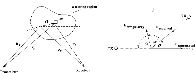
Figure 3.1: Geometry of scatter theorem analysis
The origin of the coordinate system lies within the scattering region under
observation, ![]() points to a position within this region,
points to a position within this region,
![]() and
and ![]() are the positions of the transmitter and the
receiver, respectively. They are fixed in space and can be considered
constant in this derivation. We introduce further the vectors
are the positions of the transmitter and the
receiver, respectively. They are fixed in space and can be considered
constant in this derivation. We introduce further the vectors
![]() and
and
![]() . Considered is a volume element
dV at the position
. Considered is a volume element
dV at the position ![]() . The electric field produced by the
transmitter is given by:
. The electric field produced by the
transmitter is given by:
![]()
where ![]() is the electric field at the transmitter,
is the electric field at the transmitter, ![]() is the
transmitter antenna voltage gain and
is the
transmitter antenna voltage gain and ![]() is the angular frequency of the
wave.
is the angular frequency of the
wave. The electric field at the receiver
 ![]() from the volume element dV
is then given by:
from the volume element dV
is then given by:
![]()
where ![]() is the amplitude scattering cross section of electrons for signals
incident along
is the amplitude scattering cross section of electrons for signals
incident along ![]() and scattered along
and scattered along ![]() and
and
![]() is the electron density at
is the electron density at ![]() and time t. To simplify this equation it is assumed that for a narrow
beam, the voltage gain function for the transmitting and receiving antennas can be
set to constants
and time t. To simplify this equation it is assumed that for a narrow
beam, the voltage gain function for the transmitting and receiving antennas can be
set to constants ![]() and
and ![]() respectively.
A similar simplification is done with the
scattering cross section
respectively.
A similar simplification is done with the
scattering cross section ![]() which is set to a constant, since all
spatial information is contained in the electron density term D.
The differential voltage produced at the receiver input by volume element
dV of the scatterer is then:
which is set to a constant, since all
spatial information is contained in the electron density term D.
The differential voltage produced at the receiver input by volume element
dV of the scatterer is then:
Assuming ![]() and
and
![]() , performing
a Taylor expansion on
, performing
a Taylor expansion on ![]() and
and ![]() and neglecting quadratic terms,
one obtains the following approximations for the transmitter (t)
and receiver (r) distances:
and neglecting quadratic terms,
one obtains the following approximations for the transmitter (t)
and receiver (r) distances:
![]()
![]()
This approximation can now be used to rewrite the amplitude term
![]() , but not the phase term.
Using the unit vectors
, but not the phase term.
Using the unit vectors ![]() and
and ![]() , equation
3.3 becomes:
, equation
3.3 becomes:
We express the electron density ![]() through its Fourier
component
through its Fourier
component ![]() . Thus if the transform is denoted by
. Thus if the transform is denoted by
![]() the definition of N is:
the definition of N is:
That is, by the inverse transform,
![]()
or
Substituting Equation 3.9 into Equation 3.6 yields
In these steps we also used the fact that ![]() .
If we integrate over the volume where backscatter occurs,
the
.
If we integrate over the volume where backscatter occurs,
the ![]() -dependent exponential term can be approximated by a
delta function
-dependent exponential term can be approximated by a
delta function ![]() ,
where
,
where
![]()
This means we select the component of N that corresponds
to ![]() . After the integration over
. After the integration over ![]() , taking the
delta function into account, the final result can be written as follows
, taking the
delta function into account, the final result can be written as follows
![]()
where C denotes some constant.
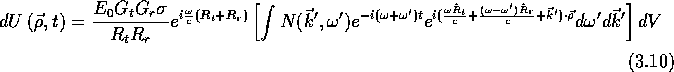
This shows that the radar is sensitive to the Fourier components of the
electron density fluctuation with wave vector ![]() ,
corresponding to the wavelength
,
corresponding to the wavelength
where ![]() is the angle between
is the angle between ![]() and
and
![]() .
This important property can be derived by considering the
following equation derived from the conservation of momentum and energy
in two dimensions (see Figure 3.1, right):
.
This important property can be derived by considering the
following equation derived from the conservation of momentum and energy
in two dimensions (see Figure 3.1, right):
and
Rewriting Equation 3.14 in terms of the wavelength ![]() for
the x and y components gives
for
the x and y components gives
Similary Equation 3.15 becomes (using 3.17)
Hence using Equation 3.16
![]()
and Equation 3.17 we get
![]()
Using some trigonometric identities this can be written as
![]()
and since ![]() is small, it follows that
is small, it follows that
![]()
But since ![]() we arrive at the property that
we arrive at the property that
which means that the angle ![]() which
which ![]() makes with
the negative x-axis is along the
bisector of the transmitter and receiver directions. Using this fact we can
write Equation 3.14 as
makes with
the negative x-axis is along the
bisector of the transmitter and receiver directions. Using this fact we can
write Equation 3.14 as
![]()
where ![]() is the unit vector pointing along the incident direction and
is the unit vector pointing along the incident direction and
![]() is perpendicular to
is perpendicular to ![]() . This can be simplified using the
following trigonometric identities
. This can be simplified using the
following trigonometric identities
![]()
![]()
![]()
![]()
to yield
![]()
By comparing the left and right side of this equation it follows that the
direction ![]() and wavelength
and wavelength ![]() is
described by:
is
described by:
![]()
![]()
We can convert ![]() to the angle
to the angle ![]() that was used earlier using
that was used earlier using
![]()
which yields Equation 3.13 again.
For a monostatic backscatter radar, with transmitting and receiving antennas
at the same location, ![]() and
and ![]() .
.